
In the Steel Joints add-on, you can classify the joint stiffness.
In addition to the initial stiffness, the table also shows the limit values for hinged and rigid connections for the selected internal forces N, My, and/or Mz. The resulting classification is then displayed in tables as "hinged", "semi-rigid", or "rigid".
Go to Explanatory Video_(2).png?mw=640&hash=0414bfe44045fc798e3774a0173332ca37424418)
General
- Beam to Column joint category: connection possible as joint of the beam to the column flange as well as joint of the column to the girder flange
- Beam to Beam joint category: design of beam joints as both moment-resisting end plate connections and rigid splice connections possible
- Automatic export of model and load data possible from RFEM or RSTAB
- Bolt sizes from M12 to M36 with strength grades 4.6, 4.8, 5.6, 5.8, 6.8, 8.8, and 10.9 as long as the strength grades are available in the selected National Annex
- Almost any bolt spacing and edge distances (a check of the allowable distances is performed)
- Beam strengthening with tapers or stiffeners on the top and bottom surfaces
- End plate connection with and without overlap
- Connection with pure bending stress, pure normal force load (tension joint), or combination of normal force and bending possible
- Calculation of connection stiffnesses and check if a hinged, semi-rigid, or rigid connection exists
End plate connection in a beam-column setup
- Joint beams or columns can be stiffened with tapers on one side or with stiffeners to one or both sides
- Wide range of possible stiffeners of the connection (for example, complete or incomplete web stiffeners)
- Up to ten horizontal and four vertical bolts possible
- Connected object possible as constant or tapered I-section
- Designs:
- Ultimate limit state of the connected beam (such as shear or tension resistance of the web plate)
- Ultimate limit state of the end plate at the beam (for example, T-stub under tensile stress)
- Ultimate limit state of the welds at the end plate
- Ultimate limit state of the column in the area of the connection (for example, column flange under bending – T-stub)
- All designs are performed according to EN 1993-1-8 and EN 1993-1-1
Moment-resisting end plate joint
- Two or four vertical and up to 10 horizontal bolt rows
- Joint beams can be stiffened with tapers on one side or with stiffeners to one or both sides
- Connected objects are possible as constant or tapered I-sections
- Designs:
- Ultimate limit state of the connected beams (such as shear or tension resistance of the web plates)
- Ultimate limit state of the end plates at the beam (for example, T-stub under tensile stress)
- Ultimate limit state of the welds at the end plates
- Ultimate limit state of the bolts in the end plate (combination of tension and shear)
Rigid splice plate connection
- For the flange plate connection, up to ten bolt rows one behind the other possible
- For the web plate connection, up to ten bolt rows possible each in vertical and horizontal directions
- Material of the cleat can be different from the one of the beams
- Designs:
- Ultimate limit state of the joint beams (for example, net cross-section in the tension area)
- Ultimate limit state of the cleat plates (for example, net cross-section under tensile stress)
- Ultimate limit state of the single bolts and the bolt groups (for example, shear resistance design of the single bolt)
.png?mw=640&hash=c1087880acc023575381bb136280b0c348568350)
- Design of hinged connections
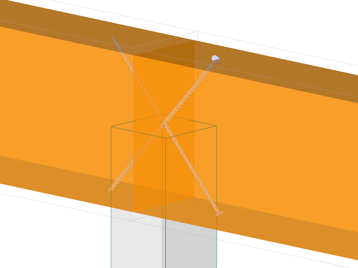
- Biaxial inclination of the connected member (for example, a jack rafter joint)
- Connection of any number of members on one node for the type "Main member only"
- Screw diameter 6 mm – 12 mm
- Automatic check of the minimum distance between screws
- Optional free definition of screw distances
- Transfer of eccentricity from RFEM/RSTAB
- Crosswise or parallel screw alignment
- Definition of up to 16 screws in a row
- Graphical visualization of joints in the add-on module and in RFEM/RSTAB
- Performing all required designs
- Design of the following geometrical types:
- Single-span beams with and without cantilevers
- Continuous beams with and without cantilevers
- Hinged girder system (Gerber beams) with and without cantilevers
- Automatic generation of wind and snow loads
- Automatic creation of required combinations for the ultimate and serviceability limit states, as well as fire resistance design
- For design according to EC 5 (EN 1995), the following National Annexes are available:
-
 DIN EN 1995-1-1/NA:2013-08 (Germany)
 -
 NBN EN 1995-1-1/ANB:2012-07 (Belgium)
 -
 DK EN 1995-1-1/NA:2011-12 (Denmark)
 -
 SFS EN 1995-1-1/NA:2007-11 (Finland)
 -
 NF EN 1995-1-1/NA:2010-05 (France)
 -
 UNI EN 1995-1-1/NA:2010-09 (Italy)
 -
 NEN EN 1995-1-1/NB:2007-11 (Netherlands)
 -
 ÖNORM B 1995-1-1:2015-06 (Austria)
 -
 PN EN 1995-1-1/NA:2010-09 (Poland)
 -
 SS EN 1995-1-1 (Sweden)
 -
 STN EN 1995-1-1/NA:2008-12 (Slovakia)
 -
 SIST EN 1995-1-1/A101:2006-03 (Slovenia)
 -
 CSN EN 1995-1-1:2007-09 (Czech Republic)
 -
 BS EN 1995-1-1/NA:2009-10 (the United Kingdom)
-
- Consideration of optimization options by user specifications according to the respective standard:
- Shear force reduction of single loads near support
- Shear force reduction of load introduction at the cross-section top point
- Moment redistribution in support zone
- Reduction of torsional stress by means of user-defined entry of moment
- Increase of bending stiffnesses for flat-ended or edgewise bending strains
- Simple geometry input with illustrative graphics
- Extensive material library for both standards
- Optional extension of material library by further materials
- Extensive library of permanent loads
- Allocation of framework to service classes and specification of service class categories
- Determination of design ratios, support forces, and deformations
- Info icon indicating successful or failed design
- Color reference scales in result tables
- Direct data export to MS Excel
- Program languages: English, German, Czech, Italian, Spanish, French, Portuguese, Polish, Chinese, Dutch, and Russian
- Verifiable printout report, including all required designs. Printout report available in many output languages; for example, English, German, French, Italian, Spanish, Russian, Czech, Polish, Portuguese, Chinese, and Dutch.
- Direct import of stp files from various CAD programs
- Design of the following column types:
- Hinged column, optionally with elastic restraint of head or footing
- Bracket, optionally with elastic restraint of footing
- Simple geometry input with illustrative graphics
- Extensive material library
- Allocation of framework to service classes and specification of service class categories
- Detailed settings of the fire resistance design
- Specification of limit deformation for the serviceability limit state design
- Determination of design ratios, support forces, and deformations
- For design according to EC 5 (EN 1995), the following National Annexes are available:
-
DIN EN 1995-1-1/NA:2013-08 (Germany)
-
NBN EN 1995-1-1/ANB:2012-07 (Belgium)
-
DK EN 1995-1-1/NA:2011-12 (Denmark)
-
SFS EN 1995-1-1/NA:2007-11 (Finland)
-
NF EN 1995-1-1/NA:2010-05 (France)
-
UNI EN 1995-1-1/NA:2010-09 (Italy)
-
NEN EN 1995-1-1/NB:2007-11 (Netherlands)
-
ÖNORM B 1995-1-1:2015-06 (Austria)
-
PN EN 1995-1-1/NA:2010-09 (Poland)
-
SS EN 1995-1-1 (Sweden)
-
STN EN 1995-1-1/NA:2008-12 (Slovakia)
-
SIST EN 1995-1-1/A101:2006-03 (Slovenia)
-
CSN EN 1995-1-1:2007-09 (Czech Republic)
-
BS EN 1995-1-1/NA:2009-10 (the United Kingdom)
- Automatic generation of wind and snow loads
- Multiple optional reductions according to the selected standard
- Direct data export to MS Excel
- Program languages: English, German, Czech, Italian, Spanish, French, Portuguese, Polish, Chinese, Dutch, and Russian
- Verifiable printout report, including all required designs. Printout report available in many output languages; for example, English, German, French, Italian, Spanish, Russian, Czech, Polish, Portuguese, Chinese, and Dutch.
- Direct import of stp files from various CAD programs
- Design of the following geometrical types:
- Single-span beams with and without cantilevers
- Continuous beams with and without cantilevers
- Hinged girder system (Gerber beams) with and without cantilevers
- For design according to EC 5 (EN 1995), the following National Annexes are available:
-
DIN EN 1995-1-1/NA:2013-08 (Germany)
-
NBN EN 1995-1-1/ANB:2012-07 (Belgium)
-
DK EN 1995-1-1/NA:2011-12 (Denmark)
-
SFS EN 1995-1-1/NA:2007-11 (Finland)
-
NF EN 1995-1-1/NA:2010-05 (France)
-
UNI EN 1995-1-1/NA:2010-09 (Italy)
-
NEN EN 1995-1-1/NB:2007-11 (Netherlands)
-
ÖNORM B 1995-1-1:2015-06 (Austria)
-
PN EN 1995-1-1/NA:2010-09 (Poland)
-
SS EN 1995-1-1 (Sweden)
-
STN EN 1995-1-1/NA:2008-12 (Slovakia)
-
SIST EN 1995-1-1/A101:2006-03 (Slovenia)
-
CSN EN 1995-1-1:2007-09 (Czech Republic)
-
BS EN 1995-1-1/NA:2009-10 (the United Kingdom)
-
- Automatic generation of wind and snow loads
- Multiple optional reductions according to the selected standard
- Simple geometry input with illustrative graphics
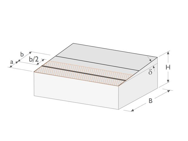
- Free entry of tapered geometries. Free selection of the grain angle allows for user-defined design of the compressive and tensile areas for bending
- Comprehensive and extensible material library
- Determination of design ratios, support forces, and deformations
- Color reference scales in result tables
- Direct data export to MS Excel
- DXF interface for preparation production documents in CAD
- Program languages: English, German, Czech, Italian, Spanish, French, Portuguese, Polish, Chinese, Dutch, and Russian
- Verifiable printout report, including all required designs. Printout report available in many output languages; for example, English, German, French, Italian, Spanish, Russian, Czech, Polish, Portuguese, Chinese, and Dutch.
- Direct import of stp files from various CAD programs
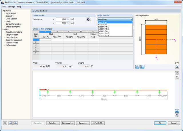
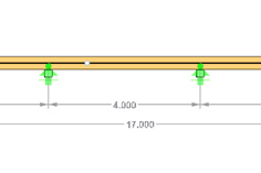
The RX- TIMBER Continuous Beam program is suitable for the design of single-span and continuous beams as well as hinged girder systems (Gerber) with or without cantilevers.
More Customer Projects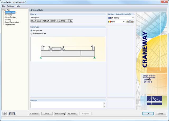
Geometry, material, cross-section, action, and imperfection data are entered in clearly arranged input windows:
Geometry
- Quick and convenient data input
- Definition of support conditions based on various support types (hinged, hinged movable, rigid, and user-defined, as well as lateral on upper or bottom flange)
- Optional specification of warping restraint
- Variable arrangement of rigid and deformable support stiffeners
- Possibility to insert hinges
CRANEWAY Cross-Sections
- I-shaped rolled cross-sections (I, IPE, IPEa, IPEo, IPEv, HE-B, HE-A, HE-AA, HL, HE-M, HE, HD, HP, IPB-S, IPB-SB, W, UB, UC, and other cross-sections according to AISC, ARBED, British Steel, Gost, TU, JIS, YB, GB, and others) combinable with section stiffener on the upper flange (angles or channels) as well as rail (SA, SF) or splice with user-defined dimensions
- Unsymmetrical I-sections (type IU) also combinable with stiffeners on the upper flange as well as with rail or splice
Actions
It is possible to consider the actions of up to three simultaneously operated cranes. You can simply select a standard crane from the library. You can also enter data manually:
- Number of cranes and crane axles (maximum of 20 axles per crane), center distances, position of crane buffers
- Classification in damage classes with editable dynamic factors according to EN 1993-6, and in lifting classes and exposure categories according to DIN 4132
- Vertical and horizontal wheel loads from self-weight, hoist load, mass forces from drive, as well as loads from skewing
- Axial loading in driving direction as well as buffer forces with user-defined eccentricities
- Permanent and variable secondary loads with user-defined eccentricities
Imperfections
- The imperfection load applies in compliance with the first natural vibration mode - either identically for all load combinations to be designed, or individually for each load combination, as mode shapes may vary depending on the load.
- Convenient tools available for scaling the mode shapes (rise determination of inclination and precamber).
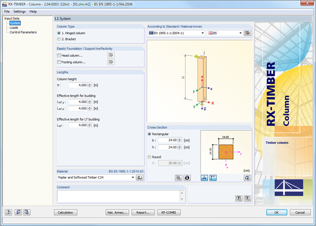
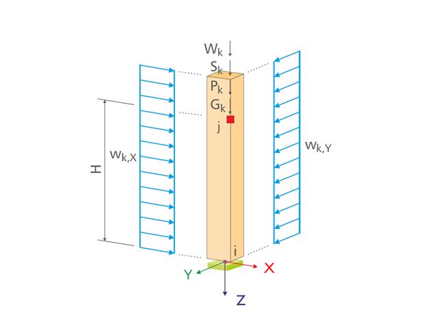
RX- TIMBER Column designs hinged columns (optionally with elastic head or footing restraint) and brackets (optionally with elastic foundation of the footing column).
For this, circular and rectangular cross‑sections are available in the program.
RX-TIMBER Column | Design of Timber Columns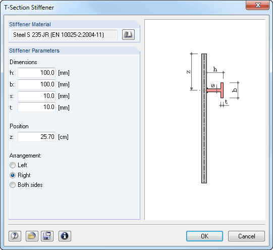
Initially, it is necessary to define material data, panel dimensions, and boundary conditions (hinged, built-in, unsupported, hinged-elastic). It is possible to transfer the data from RFEM/RSTAB. Then, boundary stresses can be either defined for each load case manually or imported from RFEM/RSTAB.
Stiffeners are modeled as spatially effective surface elements that are eccentrically connected to the plate. Therefore, it is not necessary to consider the stiffener eccentricities by effective widths. The bending, shear, strain, and St. Venant stiffness of stiffeners as well as the Bredt stiffness of closed stiffeners is determined automatically in a 3D model.
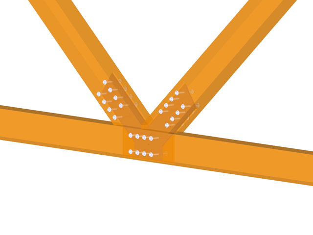
- Design of hinged, bending resistant, and semi-rigid connections
- Definition of up to 5 steel plates slotted in timber beams
- Up to 8 members connected to one node
- Thickness of steel plate 5 mm – 40 mm
- All sizes of fasteners
- Automatic check of the minimum distance between fasteners
- Optional free definition of fastener distances
- Definition of asymmetrical fastener arrangements (for example, any polygonal chains)
- Graphical visualization of joints in the add-on module and in RFEM/RSTAB
- All required steel and timber designs, including reduction of cross‑section values
- Design of transversal tension reinforcement (for EN 1995‑1‑1 only)
- Export of the member eccentricities to RFEM/RSTAB to be considered in the determination of internal forces
- Dowel length optionally shorter than cross-section width (for wooden plugs)
- DXF Export of Connection Geometry
- Fire resistance design according to EN 1995‑1‑2
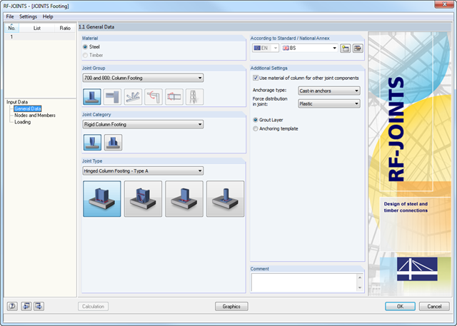
The Hinged Column Footing category provides four different base plate connections:
- Simple column base
- Tapered column base
- Column base for rectangular hollow sections
- Column base for circular hollow sections
The Restraint Column Footing category provides five different joint layouts of I-sections:
- Base plate without stiffening
- Base plate with stiffeners in center of flanges
- Base plate with stiffeners on both sides of column
- Base plate with channel sections
- Pocket foundation
All connection types include a base plate welded around a steel column. Connections with anchors are set in concrete within the foundation. You can select anchor types M12 – M42 with steel grades of 4.6 – 10.9. The top and bottom sides of the anchors can be provided with round or angled sheets for better load distribution or anchorage. In addition, you can use rectangular or circular anchor heads with threads applied at the member ends.
The material and thickness of the grout layer, as well as the dimensions and material of the footing, can be set freely. Furthermore, you can define edge reinforcement of the footing. For a better transfer of shear forces, it is possible to arrange a shear key (cleat) on the bottom side of the base plate.
Shear forces are transferred by a cleat, anchors, or friction. You can combine the individual components.